Introduction
The architecture of the flight control system, essential for all flight operations, has significantly changed throughout the years. Soon after the first flights, articulated surfaces were introduced for basic control, operated by the pilot through a system of cables and pulleys. This technique survived for decades and is now still used for small airplanes.
The introduction of larger airplanes and the increase of flight envelopes made the muscular effort of the pilot, in many conditions, not sufficient to contrast the aerodynamic hinge moments consequent to the surface deflection; the first solution to this problem was the introduction of aerodynamic balances and tabs, but further grow of the aircraft sizes and flight enveops brought to the need of powered systems to control the articulated aerodynamic surfaces.
tail trimming, etc.
Modern aircraft have often particular configurations, typically as follows:
• elevons on delta wings, for pitch and roll control, if there is no horizontal tail;
• flaperons, or trailing edge flaps-ailerons extended along the entire span:
• tailerons, or stabillisers-ailerons (independently controlled);
• swing wings, with an articulation that allows sweep angle variation;
• canards, with additional pitch control and stabilisation
Primary flight control capability is essential for safety, and this aspect is dramatically emphasized in the modern unstable (military) airplanes, which could be not controlled
Secondary actuation system failure can only introduce flight restriction, like a flapless landing or reduction in the max angle of attack; therefore it is not necessary to ensure full operation after failures.
Direct mechanical control :
Two types of mechanical systems are used: push-pull rods and cable-pulley.
In the first case a sequence of rods link the control surface to the cabin input. Bell-crank levers are used to change the direction of the rod routings sketches the push-pull control rod system between the elevator and the cabin control column; the bell-crank lever is here necessary to alter the direction of the transmission and to obtain the conventional coupling between stick movement and elevator deflection (column fwd = down deflection of surface and pitch down control) Push-pull rod system for elevator control
the pulleys are used to alter the direction of the lines, equipped with idlers to reduce any slack due to structure elasticity, cable strands relaxation or thermal expansion. Often the cable-pulley solution is preferred, because is more flexible and allows reaching more remote areas of the airplane.
Cables and pulleys system for elevator control
Hydraulic control
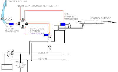
When the pilot’s action is not directly sufficient for a the control, the main option is a powered system that assists the pilot.
A few control surfaces on board are operated by electrical motors: as already discussed in a previous chapter, the hydraulic system has demonstrated to be a more suitable solution for actuation in terms of reliability, safety, weight per unit power and flexibility, with respect to the electrical system, then becoming the common tendency on most modern airplanes: the pilot, via the cabin components, sends a signal, or demand, to a valve that opens ports through which high pressure hydraulic fluid flows and operates one or more actuators.
The basic principle of the hydraulic control is simple, but two aspects must be noticed when a powered control is introduced:
1. the system must control the surface in a proportional way, i.e. the surface response (deflection) must be function to the pilot’s demand (stick deflection, for instance);
2. the pilot that with little effort acts on a control valve must have a feedback on the manoeuvre intensity.
The first problem is solved by using (hydraulic) servo-mechanisms, where the components are linked in such a way to introduce an actuator stroke proportional to the pilot’s demand; many examples can be made, two of them are sketched in fig, the second one including also the hydraulic circuit necessary for a correct operation.
In both cases the control valve housing is solid with the cylinder and the cabin column has a mechanical linkage to drive the valve spool.
Fly-By-Wire
The flight data used by the system mainly depend on the aircraft category; in general the following data are sampled and processed:
• pitch, roll, yaw rate and linear accelerations;
• airspeed/mach number, pressure altitude and radio altimeter indications;
• stick and pedal demands;
• other cabin commands such as landing gear condition, thrust lever position, etc.
The full system has high redundancy to restore the level of reliability of a mechanical or hydraulic system, in the form of multiple (triplex or quadruplex) parallel and independent lanes to generate and transmit the signals, and independent computers that process them; in many cases both hardware and software are different, to make the generation of a common error extremely remote, increase fault tolerance and isolation; in some cases the multiplexing of the digital computing and signal transmission is supported with an analogue or mechanical back-up system, to achieve adequate system reliability.
The fly-by-wire layout for the Airbus 340. Three groups of personal computers are used on board: three for primary control (FCPC), two for secondary control (FCSC) and two for high lift devices control (SFCC). The primary and secondary computers are based on different hardware; computers belonging to the same group have different software.
Two additional personal computers are used to store flight data.
 A340 fly-by-wire layout, including hydraulic system indications
 In the drawing the computer group and hydraulic system that control each surface are indicated (there are three independent hydraulic systems on the A340, commonly indicated as Blue, Yellow and Green). The leading edge flaps are linked together, and so are the trailing edge flaps, and then they are controlled by hydraulic units in the fuselage.


